tomwer axis#
Purpose#
The tomwer axis command is provided to launch the application, allowing the computation of the center of rotation from either a scan (–scan-path) or a couple of files (–file1, –file2). In the future, this should be replaced by URLs.
Warning
tomwer displays the value of the center of rotation (CoR) in \([- \frac{framewidth}{2}, \frac{framewidth}{2}]\), but nabu takes the CoR value in \([0, framewidth]\). So if you want to use this value and pass it to nabu or PyHST2, you should add \(\frac{framewidth}{2}\) to this value.
Usage#
tomwer axis [-h] [--scan-path scan_path --file1 file1 --file2 file2 --use-sinogram]
Options#
scan-path             Path to the acquisition folder that we want to observe. This should be the preferred way to launch axis.

file1                 Path to the file containing the first radiograph or sinogram to use as input. Fabio should be able to open it.

file2                 Path to the file containing the second radiograph or sinogram to use as input. Fabio should be able to open it.

use-sinogram          Use the sinogram to compute the center of rotation.

-h, --help            Show this help message and exit.
Examples of Usage#
tomwer axis --scan-path path_to_my_scan/
tomwer axis --scan-path path_to_my_scan/ --use-sinogram
Center of Rotation from Radiographs#
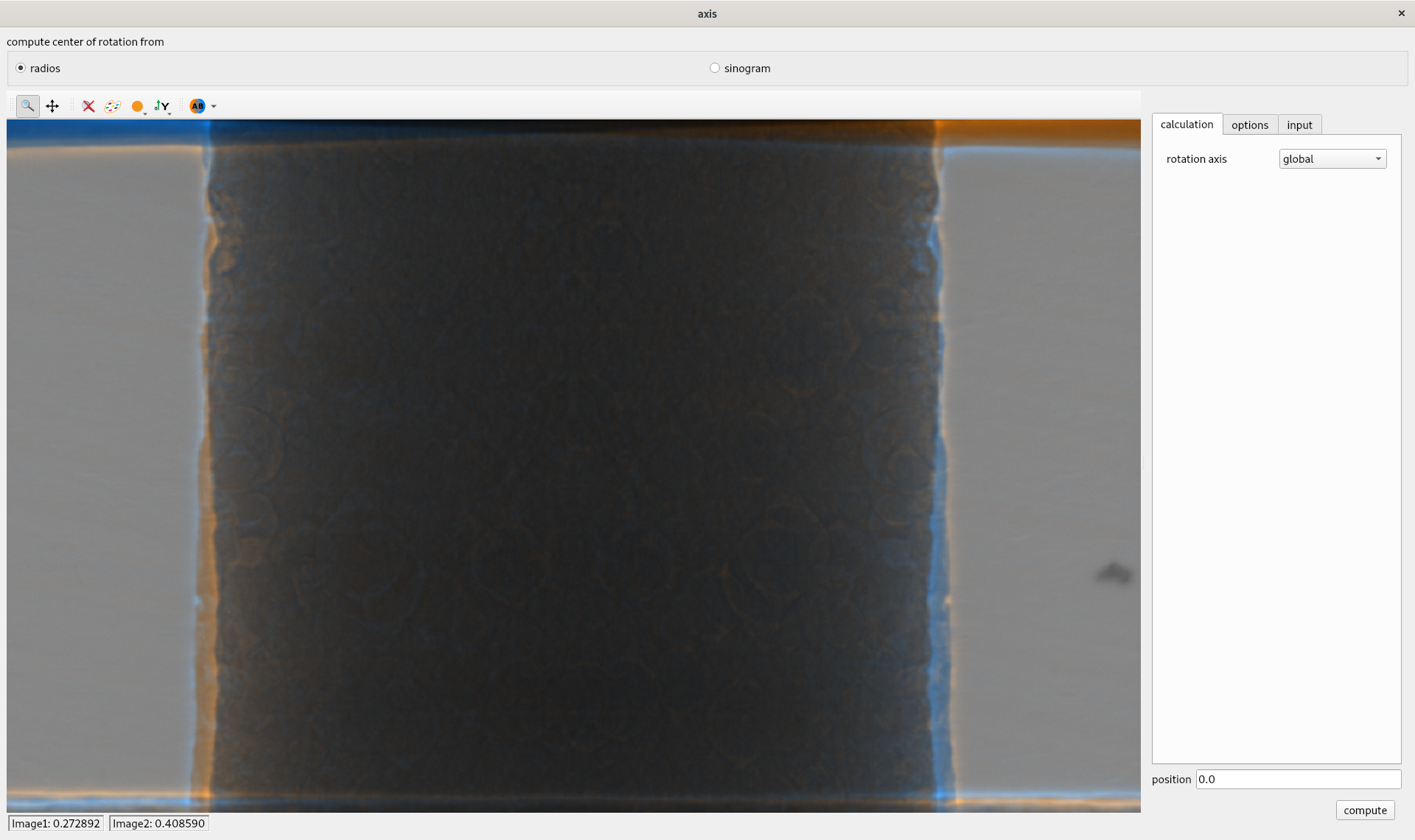
The interface for computing the center of rotation from radiographs is shown below:

The options for the center of rotation calculation are divided into three parts:
calculation: used to define the algorithm and some mandatory parameters (e.g., the near position for the near algorithm).
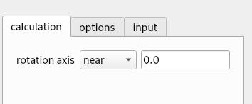
At the bottom of this section, you will find descriptions of the different algorithms. Here are some key points:
read: Allows you to read a center of rotation from a text or tomwer.h5 file.
manual: Allows you to enter a value manually.
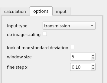
options: Defines some advanced controls for the algorithm. The available options depend on the selected algorithm.
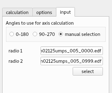
input: Defines the projection used for center of rotation calculation. The ‘0-180’ and ‘90-270’ angle modes deduce the closest projections to 0 and 180 degrees or 90 and 270 degrees, respectively. The third option allows manual selection of projections.
Center of Rotation from Sinograms#
The interface for computing the center of rotation from sinograms is shown below:
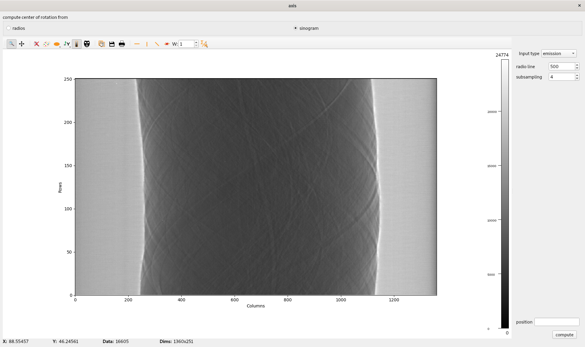
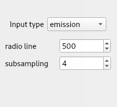
For sinograms, you should first select the type (emission or transmission). The algorithm requires log values for transmission sinograms. Then, you can pick a radiograph line and, upon selecting ‘compute’, it will: * Extract the sinogram for the selected line. * Compute the center of rotation for this line.
You can also select the subsampling value. Since datasets can be large, subsampling allows you to take every nth line.
Algorithms#
centered#
A fast and simple auto-CoR method. It only works when the CoR is near the middle of the detector. It does not work for half-tomography.
Displacement of motor = (L1 / L2 * ps) * v.
global#
A slow but robust auto-CoR method.
sliding-window#
Semi-automatically finds the CoR with a sliding window. You must specify on which side the CoR is (left, center, right). Please refer to the ‘cor_options’ parameter.
growing-window#
Automatically finds the CoR with a sliding-and-growing window. You can fine-tune the parameters using ‘cor_options’.
sino-coarse-to-fine#
Estimates the CoR from a sinogram. This only works for 360-degree scans.
composite-coarse-to-fine#
Estimates the CoR from composite multi-angle images. This only works for 360-degree scans.